

It is virtually impossible for the combined State Plane coordinate factors, also known as grid factors, to be the same throughout a project, nevertheless it has become common practice in recent years to ignore this fact. It has also become common practice to express such projects in coordinates that are not on the State Plane at all. These are euphemistically known as ground coordinates. In both cases as the projects grow larger the resulting discrepancies become substantial. Here is why.
When using State Plane coordinates the scale factors, also known as the K factors, are ratios that can be used as multipliers to convert ellipsoidal lengths, also known as geodetic distances, to lengths on the map projection surface, also known as grid distances, and vice versa. In other words, the geodetic length of a line, on the ellipsoid, multiplied by the appropriate scale factor will give you the grid length of that line on the map. And the grid length multiplied by the inverse of that same scale factor would bring you back to the geodetic length again.
A typical State Plane Coordinate zone is represented by a grid plane of projection cutting through the ellipsoid of reference. There, a distance from one point to another is longer on the ellipsoid than on the grid. This means that right in the middle of a SPCS zone the scale factor is at its minimum. In the middle a typical minimum SPCS scale factor is not less than 0.9999, though there are exceptions. Outside of the intersections the grid is above the ellipsoid where a distance from one point to another is shorter on the ellipsoid than it is on the grid. There at the edge of the zone a maximum typical SPCS scale factor is generally not more than 1.0001, but again there are now exceptions.

To illustrate the use of these factors consider line b to have a length on the ellipsoid of 130,210.44 feet, a bit over 24 miles. That would be its geodetic distance. Suppose that the scale factor for that line was 0.9999536, then the grid distance along line b would be:
Geodetic Distance ∗ Scale Factor = Grid Distance
130,210.44 ft. * 0.999953617 = 130,204.40 ft.
On the Lambert projection an east–west line, that is a line that follows a parallel of latitude, has the same scale factor at both ends and throughout. However, a line that bears in any other direction will have a different scale factor at each end. A north–south line will have a great difference in the scale factor at its north end compared with the scale factor of its south end. In this vein, here is an approximate formula.
![]()
Where K is the scale factor for a line, K1 is the scale factor at one end of the line and K2 is the scale factor at the other end of the line. Scale factor varies with the latitude in the Lambert projection. For example, suppose the point at the north end of the 24-mile line is called Stormy and has a geographic coordinate of:
37º46’00.7225”
103º46’35.3195”
and at the south end the point is known as Seven with a geographic coordinate of:
37º30’43.5867”
104º05’26.5420”
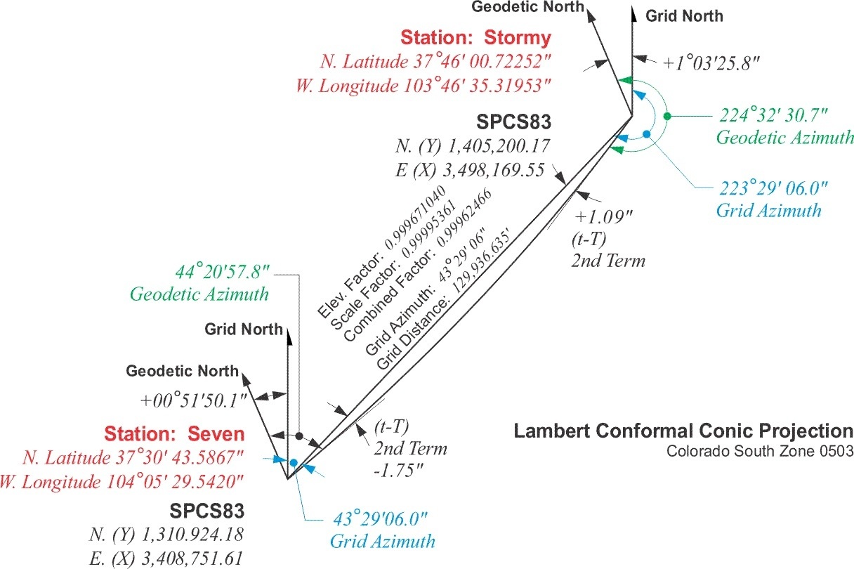
The scale factor for point Seven is 0.99996113 and the scale factor for point Stormy is 0.99994609.
![]()
![]()
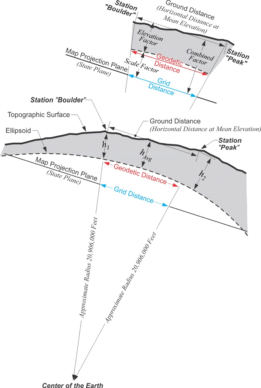
But that is not the whole story when it comes to reducing distance to the State Plane Coordinate grid. Measurement of lines must always be done on the topographic surface of the earth, and not on the ellipsoid. Therefore the first step in deriving a grid distance must be moving a measured line from the earth to the ellipsoid. In other words, converting a distance measured on the topographic surface to a geodetic distance on the reference ellipsoid. This is done with another ratio that is also used as a multiplier called the elevation factor.
This ratio is the relationship between an approximation of the earth’s radius and that same approximation with the mean ellipsoidal height of the measured line added to it. For example, consider station Boulder and station Peak.
Boulder
39º59’29.1299”
105º15’39.6758”
Peak
40º01’19.1582”
105º30’55.1283”
The distance between these two stations is 72,126.21 feet. The ellipsoidal height of Boulder, h1, is 5437 feet. The ellipsoidal height of Peak, h2, is 9099 feet. The approximate radius of the earth, traditionally used in this work, is 20,906,000 feet. The elevation factor is calculated:
Elevation Factor ![]()
Elevation Factor ![]()
Elevation Factor ![]()
Elevation Factor = 0.99965247
This factor then is the ratio used to move the ground distance down to the ellipsoid, down to the geodetic distance.
Ground Distance Boulder to Peak = 72,126.21 ft.
Geodetic Distance = Ground Distance ∗ Elevation Factor
Geodetic Distance = 72,126.21 ∗ 0.99965247
Geodetic Distance = 72,101.14 ft.
These two steps, first from ground distance to geodetic distance using the elevation factor and second from geodetic distance to grid distance using the scale factor, can be combined into one. Multiplying the elevation factor and the scale factor produces a single ratio that is usually known as the combined factor or the grid factor. Using this grid factor the measured line is converted from a ground distance to a grid distance in one jump. Here is how it works. In the example above the elevation factor for the line from Boulder to Peak is 0.99965247 and the scale factor is 0.99996590:
Grid Factor = Scale Factor * Elevation Factor
0.99961838 = 0.99996590 * 0.99965247
Then using the grid factor the ground distance is converted to a grid distance.
Grid Distance = Grid Factor * Ground Distance
72,098.68 ft. * 0.99961838 = 72,126.21 ft.