This week we’re going to take an introductory look at the measurement principles of terrestrial laser scanning. Some of the conversations we’ve had at SPAR 2004 and other events over the past few weeks lead us to believe there’s still some confusion about how these devices work. Next week we’ll talk about the best applications for each kind of device; they’re quite different.All laser scanning devices operate by first shining a focused laser light on the object being measured, then detecting and measuring the signal from light reflected by the object. In this sense, laser scanning is analogous to flash photography, taken one point at a time. Unlike
conventional photography, which records images reflected from ambient light, laser scanning and flash photography come with their own light sources.
Terrestrial laser scanners come in two flavors: time-of-flight (TOF) devices and phase-based devices. Actually, the latter are more correctly termed modulation-based (MB) devices. Phase-based lasers are the technology used in total stations, digital theodolites and interferometers,
but the term phase-based is widely used to refer to modulation-based 3D laser scanners as well. (There is a third type, optical triangulation, which is characterized by short range [usually less than one meter, though one commercial device has specified range up to 25 meters],
very high accuracy, and slow data collection rates. Triangulation is the technology least often used for terrestrial applications, and will not be discussed further here.)
Time-of-flight scanners
Devices in the first class, time-of-flight scanners, operate by emitting a pulse of light along a vector determined by two angles. It’s a little like shining a flashlight at a cat in a tree and measuring the angle from the ground – a zenith angle or elevation – and also measuring the angle from due north as measured by a compass, the azimuth angle.
We start our stopwatch when we emit the pulse of light, and we stop the watch when we detect a return signal at our sensor, which is located very close to the light source. We calculate the time taken by the light pulse, and divide by two to find the distance from the source to the reflecting
object. We record this range, along with the two angles, and we have our first point.
Simple, huh? In a billionth of a second light travels 11.8 inches, so we need an extremely fast and accurate counter. We repeat this procedure by changing the zenith and azimuth angles where we point the light, and thus capture an image point by point. Typically this procedure is repeated a few thousand times a second, creating millions of measurements in the course of a single scan.
Why doesn’t the light just bounce away?
But wait a minute. If we’re measuring the reflected light from an object that isn’t right in front of us, why do we get any signal? Doesn’t the light just bounce away – angle of incidence equals angle of refraction and all that high school physics stuff?
The answer is no – the objects we’re measuring are typically rough, at least at length scales comparable to the wavelength of the laser light used in these devices. This means there is nearly always some component of the surface we’re measuring that is normal to the light source.
Doesn’t that mean only a tiny bit of the light gets reflected to the detector? Yes indeed. But laser light is monochromatic, i.e., all one frequency, so we can filter the light seen by the detector to measure just the signal reflected by the object we’re measuring.
The reflected signal is tiny – as much as 100 db less than the transmitted signal. That’s like listening for a whisper across the room when a jumbo jet’s taking off a hundred feet away. It’s not easy, but it is possible. (Have you wondered why these devices cost as much as they do?)
Phase-based scanners
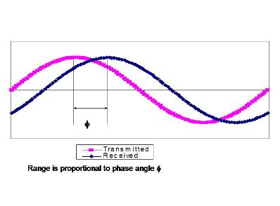
What about the other kind, modulation-based (MB) devices, often referred to as phase-based? Instead of pulsing the light source on and off, phase-based devices emit a continuous signal and modulate its amplitude or frequency – that is, the intensity or frequency is modulated by making the sine wave taller or longer.
As with time-of-flight devices, this signal is reflected by the object being measured. We measure the phase differences between the transmitted signal and the reflected signal. It turns out that the range – the distance we’re measuring – is proportional to out-of-phase angles. Today’s electronics can measure the difference in angles to about 1 part in 20,000. This angle correlation determines the distance accuracy of the system. The wavelength of the signal that modulates the amplitude or
frequency of the transmitted signal is tightly controlled and well known. For the kinds of devices we see in our industry, this might be from 0.1 meter to 20 meters. This wavelength fixes the maximum distance we measure with these devices. At the detector, we can’t distinguish between light reflected from one wave of the transmitted signal to the next, so we gate the measurement to look only at reflections from the first transmitted wave; this is the ambiguity interval.
Another methodology is to have complex modulation characteristics, in which multiple frequencies (waveforms) are transmitted, and combined to form an integrated ambiguity distance, which is longer than any of the wavelengths transmitted. This technique generally allows for higher accuracies, as the approximately 1:20,000 angle correlations are calculated over shorter waveforms; that is, 1/20,000 of a 1-meter wave is a smaller number, with better resolution, than 1/20,000 of a 10-meter wave.
With the modulation of the continuous beam occurring millions of times a second, typical speeds of capture are above 100,000 measurements per second, resulting in very large data sets with very high resolution and details like images from digital cameras.
Next week’s SparView will focus on applications where TOF measurement is best applied, and those where phase-based measurement is best applied. Hint: time-of-flight devices come from Callidus, Leica, Optech, Riegl and Trimble, and phase-based devices come from iQvolution, Visi Image and Z+F. Z+F also supplies the phase-based device that Leica OEMs as HDS 4500. Quantapoint scanners are also phase-based measurement devices.